CAD vs CAM vs CAE: The Three Software Superpowers of Modern Engineering
Not long ago, engineers designed products on paper, built clay models, and tested prototypes by trial and error. A design change meant redrawing every view, and a failed test meant starting over. Today, almost every product you touch, from a toothbrush to a jet engine, was born inside a computer, shaped by three families of software that work together as a team: CAD, CAM, and CAE.
These three acronyms are often confused, and for good reason: they sound alike, they work together, and modern software packages blur the lines between them. But each one plays a distinct role. Understanding CAD vs CAM vs CAE is like understanding the difference between a designer, a machinist, and a test engineer. Let’s meet all three.
CAD: Drawing the Product
CAD stands for computer-aided design. It is the software used to create the digital model of a product, its geometry, dimensions, and appearance. If the product is a physical object, CAD is where it starts to exist.
Modern CAD software, like SolidWorks, Fusion 360, CATIA, and NX, creates three-dimensional models that are far more than pretty pictures. A CAD model contains the exact geometry, every hole, fillet, and surface, stored as mathematical data. It can be rotated, sectioned, measured, and analyzed. It carries metadata like material, weight, and design intent. And it is the master document that downstream software uses.
CAD has evolved from simple 2D drafting into parametric modeling, where features are defined by parameters and relationships. Change one dimension, and the whole model updates. Engineers use parametric models to explore design variations quickly, and assembly tools let them check how hundreds of parts fit together.
CAD is also becoming smarter. Generative design tools, powered by AI, can explore thousands of design options automatically, finding shapes that meet performance goals while using less material. The engineer sets the requirements, and the software proposes optimized geometry. This is a glimpse of how CAD is evolving, but at its core, CAD is still the language of design, the place where a product’s shape is defined.
CAE: Testing the Product Before It Exists
CAE stands for computer-aided engineering. It is the software used to simulate and analyze how the design will behave in the real world, before any physical part exists. If CAD is the design, CAE is the virtual test lab.
The most common CAE discipline is finite element analysis, or FEA, which divides a model into millions of tiny elements and calculates how they respond to loads. FEA can predict stress, strain, and deformation, telling the engineer whether a part will bend, crack, or break under load. It can also analyze vibration, heat transfer, and fluid flow through computational fluid dynamics, or CFD.
CAE answers questions that would be expensive or impossible to answer with physical testing alone. Will this bracket survive a 10g impact? How much will this housing deform under temperature? Will this cooling channel provide enough flow? Will this beam resonate at the motor’s operating frequency? Each question can be answered in simulation, often in hours, before a single prototype is built.
The result is a dramatic reduction in physical prototypes and testing. Instead of building and breaking ten versions of a part, engineers simulate ten versions and build only the winner. CAE also reveals problems that testing might miss, like hidden stress concentrations, and it provides deep insight into why a design behaves the way it does.
Modern CAE is closely connected to CAD. The CAD model feeds directly into the simulation, and the results are visualized on the model itself, with color maps showing stress hot spots. The line between design and analysis is blurring, but the discipline is distinct: CAD creates, CAE verifies.
CAM: Making the Product
CAM stands for computer-aided manufacturing. It is the software that turns a design into instructions for machines. If CAD is the blueprint and CAE is the test, CAM is the machine operator, translating the geometry into the toolpaths that cut, shape, or print the part.
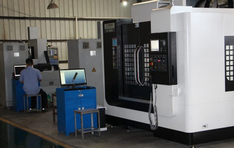
The heart of CAM is toolpath generation. For a CNC mill, CAM software calculates the exact paths the cutting tool must follow to machine the part from a block of material: where to cut, how fast, how deep, and in what order. It selects tools, sets speeds and feeds, and optimizes the sequence to minimize machining time while protecting the tool and the part.
CAM is not limited to machining. It generates the laser paths for cutting, the print paths for 3D printers, the bending sequences for sheet metal, and the wire paths for EDM. Whatever the manufacturing process, CAM software converts the CAD geometry into the machine’s native language, usually G-code, the instruction set that controls the machine’s movements.
Good CAM work is an art as much as a science. The same part can be machined a dozen different ways, with different tools, strategies, and cycle times. A skilled CAM programmer chooses roughing strategies that remove material fast, finishing strategies that leave a smooth surface, and cutting parameters that protect the tool. The result is a part that is accurate, fast to make, and gentle on the machine.
How the Three Work Together
The real power of CAD, CAM, and CAE appears when they work as an integrated pipeline. A typical product development workflow looks like this.
The engineer designs the part in CAD, defining the geometry that meets the functional requirements. The model is passed to CAE, which simulates the part under real-world loads. The simulation reveals weak points, so the engineer adjusts the design. The improved model goes back to CAE for another round, and the cycle repeats until the design is robust.
Once the design is approved, the model goes to CAM. The CAM programmer creates toolpaths, simulates the machining to check for collisions, and posts the G-code for the machine. The part is manufactured, inspected, and compared to the CAD model. Any discrepancy feeds back into the process, improving both the design and the manufacturing strategy.
This digital thread, from design to simulation to manufacturing, is the foundation of modern product development. It allows engineers to iterate quickly, catch problems early, and bring better products to market faster. The tighter the integration, the fewer surprises on the factory floor.
The Blurring Lines
While CAD vs CAM vs CAE are conceptually distinct, modern software is blurring the boundaries. Integrated platforms like Fusion 360 combine CAD, CAM, and CAE in a single application, so a designer can model, simulate, and generate toolpaths without leaving the environment.
This integration is a huge benefit for small teams and independent engineers, who can afford one platform instead of three. It also improves the workflow, because data does not need to be exported and converted between programs, a step that often caused errors.
The trend is accelerating with cloud computing and AI. Design optimization, once a separate CAE task, is being embedded in CAD. Machining knowledge is being embedded in CAM, with software suggesting optimal strategies based on the geometry and material. And simulation is becoming so fast that engineers can test dozens of variants in the time it once took to test one.
Choosing the Right Software
If you are starting out or evaluating tools, the right choice depends on your role. If you are a designer, invest in strong CAD skills; they are the foundation. If you are an engineer responsible for structural integrity, add CAE skills and learn to interpret simulation results critically. If you work on the shop floor or in manufacturing engineering, CAM expertise is your superpower.
For hobbyists and small businesses, integrated platforms like Fusion 360 offer the best value, combining all three disciplines affordably. For large enterprises, specialized high-end systems like CATIA, NX, and Abaqus offer depth that integrated platforms cannot match. The important thing is to understand what each tool is for, and to know how the pieces fit together.
The Bigger Picture
CAD, CAM, and CAE are not competing technologies; they are a team. CAD imagines, CAE verifies, and CAM builds. Together, they have compressed the product development cycle from years to months, reduced the need for physical prototypes, and made it possible to design and manufacture products of astonishing complexity.
The next time you hold a beautifully engineered product, a laptop with a perfectly fitting hinge, a car with a quiet, durable drivetrain, a phone with a sealed, rugged body, remember the invisible pipeline behind it. Somewhere, a designer shaped it in CAD, an analyst proved it in CAE, and a machinist or mold maker built it with CAM. The three software superpowers of modern engineering, working as one.